Select Page

Electrical Harness from 334 to 3832 kgm
Electrical Harness DEH

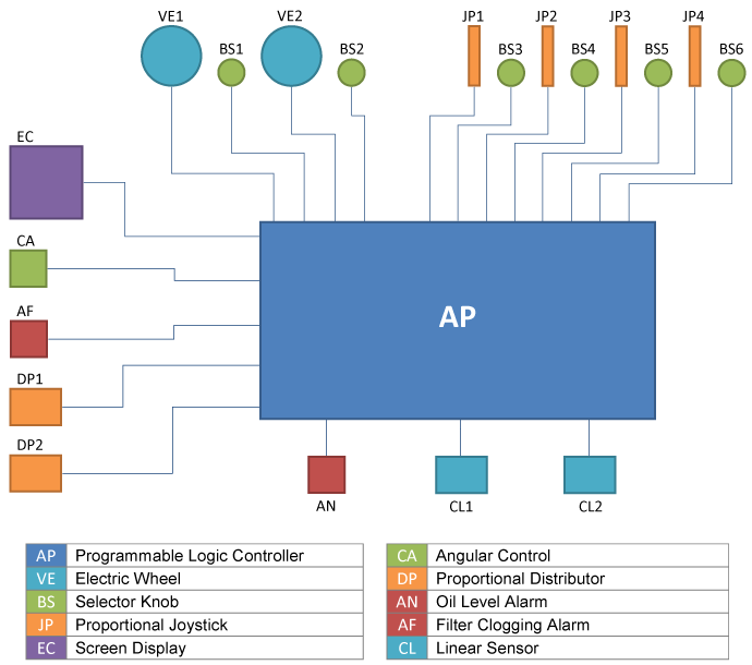
The electrical harness consists of all electrical wires connecting the transmitters and receivers to the programmable logic controller. Its definition depends on the number and type of steering system components and on the distances between these components and the programmable logic controller.

Each wire is fitted on both ends with paired pre-swaged connector halves.

Example Electrical Harness Setup

Specifications of the steering system:
Twin steering station + 1 joystick + 3 selector knobs + 1 screen display + 1 programmable logic controller + 2 cylinders/linear sensors + 1 power pack + 1 equipped tank + 1 double proportional distributor (double cylinder).

Define the individual wire lengths on the above diagram:
VE1/AP ; BS1/AP ; V2/AP ; BS2/AP
JP1/AP ; BS3/AP
EC/AP
DP1/AP ; DP2/AP
AN/AP ; AF/AP
CL1/AP ; CL2/AP

Selection of Steering System from 334 to 3832 kgm

Steering System with Single Cylinder

Single Steering StationDouble Steering Station
2203400*Electric Wheel (2.5 turns)1N/A
2203287*540° Electric Wheel12
2203288Proportional Joystick (FFU)1 to 41 to 4
2203296Selector Knob1 to 52 to 6
2203403*Angular Control1 or more1 or more
2203295Screen Display11
2203961Programmable Logic Controller11
Analog transmitters. Maximum three transmitters of all types per system.
Example of a Steering System Setup
Specifications of the steering system: 900 kgm rudder torque – Double steering station + 1 Joystick – Voltage available: single-phase 230V / 50 Hz
Parts to Select:
2 540° Electric wheels2203287
1 Proportional joystick (FFU)2203288
3 Selector knobs2203296
1 Screen display2203295
1 Programmable logic controller2203961
1 Cylinder + sensor2203442
1 Equipped Tank2203426
1 Single-phase hydraulic power pack2203418
1 Single proportional distributor2203432
1 Tiller arm2203303
1 Electrical harness / 1 Hydraulic pipingLengths to be determined
Torque in kgm 334435588790100015521916
Cylinder + Sensor2203438220343922034402203441220344222034442203445
Hydraulic Power Pack – 3-phase2203412220341222034122203413220341322034142203415
Equipped Tank2203425220342522034252203426220342622034262203427
Single Proportional Distributor2203431220343122034322203432220343222034322203433
Hydraulic Power Pack – 1-phase2203417220341722034172203418220341822034192203419
Equipped Tank2203425220342522034252203426220342622034262203426
Single Proportional Distributor2203431220343122034312203432220343222034322203432
Hydraulic Power Pack 24 Vcc2203409220340922034102203410220341122034112203411
Equipped Tank2203425220342522034252203425220342622034262203426
Single Proportional Distributor2203431220343122034322203432220343222034322203432
Tiller Arm2203300220330122033022203302
2203303
220330322033052203305
Electrical Harness / Hydraulic Piping: in function of the steering system setup .

Steering System with Double Cylinder

Single Steering StationDouble Steering Station
2203400*Electric Wheel (2.5 turns)1N/A
2203287*540° Electric Wheel12
2203288Proportional Joystick (FFU)1 à 41 à 4
2203296Selector Knob1 to 52 to 6
2203403*Angular Control1 or more1 or more
2203295Screen Display11
2203961Programmable Logic Controller11
*Analog transmitters. Maximum three transmitters of all types per system.
Example of a Steering System Setup
Specifications of the steering system: 900 kgm rudder torque – Double steering station + 1 Joystick – Voltage available: single-phase 230V / 50 Hz
Parts to Select:
2 540° Electric wheels2203287
1 Proportional joystick (FFU)2203288
3 Selector knobs2203296
1 Screen display2203295
1 Programmable logic controller2203961
2 Cylinders + sensors2203440
1 Equipped Tank2203426
1 Single-phase hydraulic power pack2203418
1 Double proportional distributor2203434
2 Tiller arms2203302
1 Electrical harness / 1 Hydraulic pipingLengths to be determined
Torque in kgm 640870117615802000232831043832
Cylinder + Sensor22034382203439220344022034412203442220344422034442203445
Hydraulic Power Pack – 3-phase22034132203413220341322034152203415220341622034162203416
Equipped Tank22034262203426220342622034272203427220342822034282203428
Double Proportional Distributor22034342203434220343422034352203435220343622034362203436
Hydraulic Power Pack – 1-phase2203418220341822034182203419
Equipped Tank2203426220342622034262203426
Double Proportional Distributor2203434220343422034342203435
Hydraulic Power Pack 24 Vcc22034102203410220341122034112 x 22034112 x 22034112 x 22034112 x 2203411
Equipped Tank22034252203425220342622034262203428220342822034282203428
Double Proportional Distributor22034342203435220343522034352203435220343522034352203435
Tiller Arm2203300220330122033022203302
220330322033042203304
2203305
2203305
Electrical Harness / Hydraulic Piping: in function of the steering system setup .

Tiller Arms from 334 to 3832 kgm

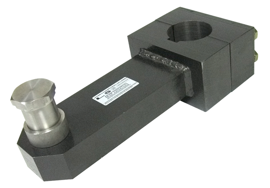
2203300 334 kgm Equipped Tiller Arm
Pilot bored Ø 20 mm – Maxi Ø 64 mm

2202472 Equipped Tiller Arm
2202472 Equipped Tiller Arm Dimensions Drawing

2203301 435 kgm Equipped Tiller Arm
Pilot bored Ø 20 mm – Maxi Ø 64 mm

2202472 435 kgm Equipped Tiller Arm
2203301 435 kgm Equipped Tiller Arm Dimensions Diagram

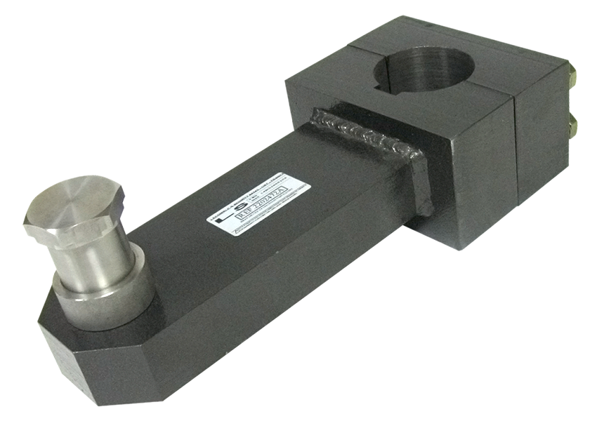
2203302 588 / 790 kgm Equipped Tiller Arm
Pilot bored Ø 20 mm – Maxi Ø 88 mm

2202472 435 kgm Equipped Tiller Arm
2203302 588 - 790 kgm Equipped Tiller Arm Dimensions Drawing

2203303 1000 kgm Equipped Tiller Arm
Pilot bored Ø 20 mm – Maxi Ø 88 mm

2202472 435 kgm Equipped Tiller Arm
2203303 1000 kgm Equipped Tiller Arm Dimensions Drawing

2203304 1164 kgm Equipped Tiller Arm
Pilot bored Ø 20 mm – Maxi Ø 88 mm
For 2328 kgm double cylinder only

2202472 435 kgm Equipped Tiller Arm
2203304 1164 kgm Equipped Tiller Arm Dimensions Drawing

2203305 1552 / 1916 kgm Equipped Tiller Arm
Pilot bored Ø 20 mm – Maxi Ø 100 mm

2202472 435 kgm Equipped Tiller Arm
2203305 1552-1916 kgm Equipped Tiller Arm Dimensions Drawing

Proportional Distributors

2203431 Proportional Distributors

Proportional Distributors
Dimensions Drawing
2203432 10 L Single Proportional Distributors
2203433 25 L Single Proportional Distributors
2203434 40 L Single Proportional Distributors
2203435 10 L Double Proportional Distributors
2203436 25 L Double Proportional Distributors
2203437 40 L Double Proportional Distributors

In accordance with the analogue order received by the programmable logic controller, the proportional hydraulic distributor will provide the flow and hydraulic pressure needed to move the cylinder(s) at the speed and to the positions commanded by the steering wheel, the joystick or any other transmitter.

In the case of a double cylinder installation, its independent modules allow for permanent synchronization of the cylinders. The modules are fitted with relief valves which protect the circuit against excessive pressure rise. They feature manual overrides in the event of a loss of power and are protected by a filter with clogging detection alarm. They can be delivered assembled on the equipped tank or separately for on-line installation between the equipped tank and the cylinders.

Equipped Tanks

Equipped Tanks

Equipped Tanks
Dimensions Drawing

Their volumes are determined by the flow rates generated by the power packs. They are fitted with filling and emptying apertures and oil level sight glass with alarm.

They also feature anchoring studs for the installation of the power packs and proportional distributors.

Depending on the system setup (see “Sélection of Steering System” menu), they can accommodate one or two power packs.

Equipped TanksABCDEF
2203425 Equipped Tank25 L32553035027548011
2203426 Equipped Tank50 L34065044035060011
2203427 Equipped Tank80 L39073050040068011
2203428 Equipped Tank120 L43086555045081511

Power Packs for Electro-Hydraulic Steering

2203410 Power Pack Support Plate

Power Packs
Dimensions Drawing

Power packs are complete assembled units consisting of an electric motor, a hydraulic pump with fittings, a coupling between the pump and the motor and a support plate. Pump and motor capacities vary in function of the volume and the number of cylinders to be driven.
Electric motors can be supplied within certain limits (see “Electro-Hydraulic Steering System with Single Cylinder” and “Electro-Hydraulic Steering System with Double Cylinder”) in 24V direct-current, single-phase or three-phase alternating current. They can be delivered assembled on the equipped tank or separately for on-line installation between the tank and the proportional distributor.

Power PacksABCDEFG
22034090.9 kW – 8 l/mn – 24 Vdc+ support plate220210150435155965
22034101.9 kW – 12 l/mn – 24 Vdc+ support plate2202401604651559105
22034113 kW – 22 l/mn – 24 Vdc+ support plate27024019554515011155
22034121.1 kW – 9 l/mn – 400 VAC 3-PHASE + support plate220250190395155945
22034132.2 kW – 17 l/mn – VAC 3-PHASE + support plate2702652004751501185
22034143 kW – 22 l/mn – VAC 3-PHASE + support plate2702652204801501185
22034154 kW – 32.5 l/mn – VAC 3-PHASE + support plate27028523553015011125
22034167.5 kW – 59 l/mn – 400 VAC 3-PHASE + support plate41033530063019011110
22034171.1 kW – 9 l/mn – 230 VAC 1-PHASE + support plate220270185420155940
2203418 2.2 kW – 17 l/mn – 230 VAC 1-PHASE + support plate2702852004751501185
2203419 3 kW – 22 l/mn – 230 VAC 1-PHASE + support plate2703002204801501180

Receivers: Cylinders / Linear Sensors

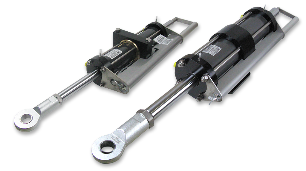
Cylinder + Linear Sensor

The cylinders provide the power of the steering system.
They are selected by using the methods described in « Sélection of Steering System » menu.

All the cylinders are supplied with their pre-assembled and adjusted linear sensors. The linear sensor is supplied pre-wired with a pre-swaged connector half.

2203438 VHM 60 DT C300 + Linear Sensor
Maximum torque334 kpm2463 ft.lbs
Stroke300 mm11 13/16″
Maximum pressure60 bars870 PSI
Volume664 cc40.5 cu.in
Radius of tiller arm252 mm9 59/64″
Total rudder angle73° (2×36.5°)
Weight18 kg39.5 lbs
Dimension Drawing for 2203438

2203439 VHM 63 DT C345 + Linear Sensor
Maximum torque435 kpm3208 ft.lbs
Stroke345 mm13 19/32″
Maximum pressure60 bars870 PSI
Volume862 cc52.6 cu.in
Radius of tiller arm290 mm11 27/64″
Total rudder angle73° (2×36.5°)
Weight27 kg59.5 lbs
Dimension Drawing for 2203439

2203440 VHM 80 DT + Linear Sensor
Maximum torque588 kpm4336 ft.lbs
Stroke300 mm11 13/16″
Maximum pressure60 bars870 PSI
Volume1167 cc71.2 cu.in
Radius of tiller arm252 mm9 59/64″
Total rudder angle73° (2×36.5°)
Weight32 kg70.5 lbs
Dimension Drawing for 2203440

2203441 VHM 90 DT + Linear Sensor
Maximum torque790 kpm5826 ft.lbs
Stroke300 mm11 13/16″
Maximum pressure60 bars870 PSI
Volume1567 cc95.6 cu.in
Radius of tiller arm252 mm9 59/64″
Total rudder angle73° (2×36.5°)
Weight37 kg81.5 lbs
Dimension Drawing for 2203441

2203442 VHM 90 DT C400 + Linear Sensor
Maximum torque1000 kpm7233 ft.lbs
Stroke400 mm15 3/4″
Maximum pressure60 bars870 PSI
Volume2090 cc128 cu.in
Radius of tiller arm336 mm13 25/32″
Total rudder angle73° (2×36.5°)
Weight47.5 kg100 lbs
Dimension Drawing for 2203442

2203443 VHM 110 DT C300 + Linear Sensor
Maximum torque1164 kpm8565 ft.lbs
Stroke300 mm11 13/16″
Maximum pressure60 bars870 PSI
Volume2307 cc141 cu.in
Radius of tiller arm352 mm 9 59/64″
Total rudder angle73° (2×36.5°)
Weight52 kg115 lbs
Dimension Drawing for 2203443

2203444 VHM 110 DT + Linear Sensor
Maximum torque1552 kpm11446 ft.lbs
Stroke400 mm15 3/4″
Maximum pressure60 bars870 PSI
Volume3076 cc87.7 cu.in
Radius of tiller arm336 mm13 25/32″
Total rudder angle73° (2×36.5°)
Weight55.5 kg122 lbs
Dimension Drawing for 2203444

2203445 VHM 120 DT + Linear Sensor
Maximum torque1916 kpm14131 ft.lbs
Stroke400 mm15 3/4″
Maximum pressure60 bars870 PSI
Volume3798 cc231.8 cu.in
Radius of tiller arm336 mm13 25/32″
Total rudder angle73° (2×36.5°)
Weight62.5 kg138 lbs
Dimension Drawing for 2203445