Select Page

Video guides for installation and maintenance of LS products

Logo Lecomble and Schmitt

We have created this section to help you with the installation and the maintenance of Lecomble & Schmitt products. You will also find all these videos on our YouTube channel: https://www.youtube.com/user/lsfrance.

Please do not hesitate to send us your comments or suggestions in order to improve and develop this section while constantly striving to fully satisfy you.

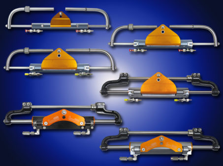
Installation of LS Cylinders for Outboards

Installation of LS Cylinders for Outboards

Maintenance of LS Outboard Helm Pumps

Maintenance of LS Outboard Helm Pumps

Maintenance of LS Outboard Helm Pumps

Maintenance of outboard helm pump type LS 20 HB

Maintenance of outboard helm pumps type LS 26/40/50 HB

Maintenance of outboard helm pumps type LS 30/35 HB

Maintenance of outboard helm pumps type LS 29/35 CT HB

Installation of LS cylinders for Outboard

Installation of LS cylinder VHM EX 80 HP

Installation of LS cylinder VHM EX 125 HP

Installation of LS cylinder VHM EX 175 HP

Installation of LS cylinder VHM EX 225 HP

Installation of LS cylinder VHM EX 350 HP

Installation of LS cylinder VHM EX 3500 HP

Filling and bleeding a hydraulic steering system

Accessories for Power Assisted Hydraulic Steering Systems

2203593 Speedy Purge
LS SPEEDY PURGE is a tool designed to fill and purge air from LS Hydraulic Steering Systems fitted on 5 to 15 metre boats.
LS SPEEDY PURGE connects directly to the 12 volt boat battery with crocodile clips and to the cylinder and pump with 2 x 4 metre clear spiral hoses.
Easily transportable, its 4 litre oil contents gives sufficient autonomy to bring 2 to 3 steering systems into service without filling up.
Fill and purge is done neatly by one technician alone in less than 10 minutes, thus ensuring that SPEEDY PURGE is paid off with the very first steering systems. LS Speedy Purge is the ideal tool for shipyards with small series of boats or for installation or maintenance work at marinas.
2203836   
LS Speedy purge – 12V – with 4 m extension hoses
1206948
Set of 2 x 4 m extension hoses
2203593 LS Speedy purge

Electrical By-pass

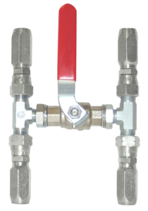
2200376 Electrical By-pass NO 06 12 VDC 3/8 BSPP
2201479 Electrical By-pass NO 06 24 VDC 3/8 BSPP
2200566 Electrical By-pass NO 12 12 VDC 1/2 BSPP
2201438 Electrical By-pass NO 12 24 VDC 1/2 BSPP
2200376 Electrical By-Pass

Lock Valves on line

2200078-Lock Valve On Line
2200078 Lock Valve On Line Dimensions Drawing
2200078 Lock Valve on line LS 115

for pumps: 30 HB-without LV, 35 HB-without LV, 40 HB-without LV, 50 HB-without LV, 70 CT-without LV, 90 CT-without LV

2200110 Lock Valve On Line LS170
2200110 Lock Valve On Line LS170 Dimensions Drawing
2200110 Lock Valve on line LS 170

for pumps: 105 CT-without LV, 150 without LV, 170 without LV, 200 CT-without LV

Adaptable Cones

2201138 Adaptable Cone + pin Ø 22 – 2°30 angle
  for pumps: 30 HB, 35 HB, 40 HB
Adaptable Cone + pin Ø 22 - 2°30 angle
2200029 Adaptable Cone + pin Ø 24.5 – 8° angle
  for pumps: 30 HB, 35 HB, 40 HB
2200029-Adaptable Cone + pin Ø 24.5 - 8° angle

Dual Pressure Relief Valve

Dual Pressure Relief Valve
Dual Pressure Relief Valve Dimensions Drawing
2203369 Dual Pressure Relief Valve

By-pass Valves – Flexible Tubes

2200803 By-pass valve–flexible tube TS 6
2202496 By-pass valve–flexible tube TS 8
2200803 By-Pass Valve Flexible Tube
2200027 By-pass valve–flexible tube Ø 8 mm
2200067 By-pass valve–flexible tube Ø 10 mm
2200027 By Pass Valve Flexible Tube
2200683 By-pass valve–inflexible tube 6 x 8
2200045 By-pass valve–inflexible tube 8 x 10
2200097 By-pass valve–inflexible tube 10 x 12
2202022 By-pass valve–inflexible tube 13 x 15
2200015 By-pass valve–inflexible tube 15 x 18
2200683 By-Pass Valve Inflexible Tube

Torque Calculation for Power Assisted Hydraulic Steering Systems

For boats fitted with a rudder, the torque of the rudder or rudders is calculated according to the following formula and corrections.

It must be known that the torque necessary  to manoeuver a boat depends on:

  • The speed of the water flowing on the surface of the rudder at a certain angle
  • The rudder size
  • The total sweep of the rudder (and part of the boat), if the rudder shaft is not perpendicular
  • The compensating surface of the rudder (balanced rudder)

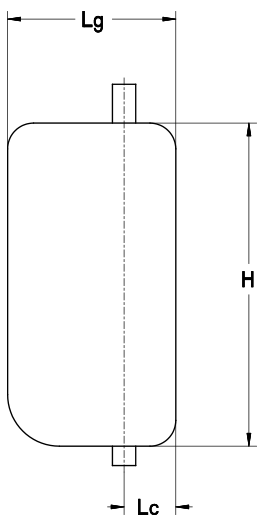
    C = S x [ (0.4 Lg) – Lc ] x V² x K

C = Torque in kgm
S = Total surface of rudder (H x Lg) in sq. m
H = Height of rudder in m
Lg = Width of rudder in m
Lc = Compensation width in m
V = Maximum speed of the boat in knots
K = Coefficient in function of total rudder angle

Port to starboard70°K = 15.89
Port to starboard80°K = 17.80
Port to starboard90°K = 19.52

Torque Diagram

Corrections in function of the type of boat:
For a boat with a steering nozzleC x 2.0
For twin engine power boats with 1 rudderC x 0.5
For boats fitted with several rudders (catamarans, monohulls)Multiply the calculated torque result by the number of rudders fitted on the boat.

Power Assisted Hydraulic Steering Systems

Specifically designed for luxury vessels getting regular and intensive use, LS range of Power Assisted Steering Systems is designed in total compliance with the strictest norms applying to marine equipment.

The recommended solutions for 185 kpm to 2.000 kpm rudder torque are suitable to equip 15 to 40 metre vessels.

Absolute security comes first: steering is still possible even in case of electrical failure.

Features such as smoothness, accuracy and reduced number of wheel turns give LS power assisted steering systems unequalled comfort.

The ease of use of the catalogue enables the shipyards engineering and design departments to define straightaway the correct system in function of the rudder torque, the power supply available on board and the number of steering stations.

Hydraulic Piping from 334 to 3832 kgm

The hydraulic piping represents all the hydraulic flexible tubes linking together the hydraulic components (equipped tank, proportional distributor, by-pass valve, cylinder…). Its definition depends on the number and type of steering system components and on the distances between these components. It also depends on the configuration of the hydraulic diagram (single or double cylinder, elements supplied on the equipped tank or separately).

Each hydraulic hose is fitted with pre-swaged fittings and union fittings on both ends.

Electro-Hydraulic Steering System with Single Cylinder
REEquipped Tank
GMPower Pack
DPSingle Proportional Distributor
BPBy-Pass Valve
VCLCylinder / Linear Sensor

1. Separate power pack and single proportional distributor

Separate power pack and single proportional distributor

1′. Power pack and single proportional distributor mounted on the equipped tank

Power pack and single proportional distributor mounted on the equipped tank
Electro-Hydraulic Steering System with Double Cylinder
REEquipped Tank
GMPower Pack
DPDouble Proportional Distributor 1 and 2
BPBy-Pass Valves 1 and 2
VCLCylinders / Linear Sensors 1 and 2

Example of Hydraulic Piping Setup

Specifications of the steering system configuration:

Electro-hydraulic steering system with double cylinder and separate elements.

In function of the chosen locations for the installation of the elements on the boat, the distances numbered 1 à 11 in the above diagram 2 must be determined.

2. Separate power pack and double proportional distributor

Separate power pack and double proportional distributor

2′. Power pack and double proportional distributor mounted on the equipped tank

Power pack and double proportional distributor mounted on the equipped tank